Business Analyst
Personal Notes
These are personal notes. You are welcome to read them.
|
|
|
|
|
Management hints
|
HTML, javascript
|
Other
|
(best practises, risks, choosing software, ...)-
(scope, design, development, rollout)
-
(details on the scope and design phase)
-
-
|
|
|
| |
|
|
|
|
|
Contents
- , with Business Requirements Document Template
- on Data Modeling page
- on Data Quality page
-
Jargon is
highlighted: use it to embellishment and to impress
In addition to the notes here, also look at the following sections in the page
on :
A lot of the material from this page comes from the Business Analyst course
given at Boston University. Other
material comes from other reading and personal experience.
The Role
Goal of the Business Analyst
- Often start with a Business Case, which has been prepared by a non-IT business
consultant.
- To conduct effective requirements
gathering interviews with users.
- To create documentation
that is comprehensive, unambiguous and reusable. The level of detail
is determined by "how much the developers need to do their job without
making wrong assumptions". Clarity is added by various typres of diagrams.
- Keep up dialogue with developers during the coding phase.
- To later ensure quality
assurance.
Sometimes, the company doesn't quite believe in the role of BA, i.e. doesn't
believe in the need for gathering requirements.
There may also be a need to earn the respect from BOTH sides (users AND developers).
Compared to the Systems Analyst, the BA defines the outside/interface of the
system whereas the Systems Analyst defines the inner workings (specifications).
Non-IT Business Analysts do not concentrate on computer system requirements.
- A business analyst should have confidence, communication skills, listening skills, and business knowledge.
- Involve the business people representing perspectives across management ranks (vertical) and across departments (horizontal). Do not rely on a single BA who is alone, however good s/he is.
- We don't know what the business wants just because we have worked with them for long.
- Though project and program requirements may look similar, the differences are in the participants and scope.
- Have direct contact with business representatives. Analysis of existing reports is not sufficient.
- Prepare interviewees in advance by explaining datawarehousing and business intelligence concepts.
Planning the Analysis
Start with a kick-off
meeting to give a formal start to the project. The goal is to create
identify the stakeholder interests and define the business use cases. Get consensus
from stakeholders. Also create team spirit with some common activity. Deliverables
are:
The next step is to analyze
the business use cases, so as to understand the context of the project.
There is probably no need to go into detail. Produce workflow descriptions and
diagrams.
Based on the previous step, identify the System Use Cases
(the automated part of the Business Use Cases). Deliverables:
- Role Map: basically a list of actors (one meeting)
- System Use Case Packages (in the same meeting as Role Map)
- System Use Case Diagrams (one meeting per business use case)
- System Use Case Briefs (same meeting as previous point)
Then flesh out the use cases and describe:
- Scenarios for each use case, without exceptions (the "happy day"
scenario)
- Context and basic flows (happy day scenario for each use case)
- Alternate and exception flows (first list the "ifs" then go into
detail of each flow)
- Special use cases (inclusions, generalizations, extensions)
Add links to additional documentation (see below)
A large part of these steps was taken from the "Noble
Path"
The analysis described here, and performed by the Business Analyst, will later
lead to a more detailed functional analysis.
Kick-off Meeting
See [3] for more tips.
Meet with with stakeholders before the meeting to understand the main issues.
Invite sponsor, subject matter experts, user representatives, developers, customer
support, quality assurance. See larger list of potential participants below.
Parts of the kick-off meeting:
- Review the charter or existing project documentation.
- Define the system
boundary, which is the part within the scope of the project.
- Define the stakeholders and interests (see below); off-stage stakeholders.
- Create business use case briefs (see Use Case Briefs below). Use verbs in
the business case name. No details. No diagrams (this comes later).
- Risk analysis: describe probability of occurrence, potential damage and
strategy. Strategies include eliminating the risk, mitigating (reducing the
damage), transfering up or out, accepting the risk.
- Define the priorities
- Define the reporting procedures for keeping the stakeholders informed (meetings/emails,
frequency)
- Define the procedures for acceptance of the project steps.
- Define process for resolving conflicts
- Approve the decisions taken as laid out in the recorded documentation.
- Give a summary of next steps so that people know what to expect.
|
Stakeholders and Interests Table
| Stakeholder |
Description |
Interest |
| |
|
|
See also Stakeholders.
|
|
Use Case Briefs
| Business Use Case |
Actors |
Brief |
| |
|
|
|
Analysis of the Business Cases
See [3] for more tips.
Use the Stakeholder and Interest Table to decide which people to invite.
Try to identify the participants in the business processes and document them
in the form of business use cases. These business use cases can contain both
manual and automated steps.
Distinguish between:
- Business Actors: outside users of the service;
- Workers: people inside the organization who carry out tasks.
- Systems. However, note that the system being designed is not an actor.
Describe the workflow and document using numbered steps.
Approval Process
"The requirements phase ends with agreement, but the requirements work
never ends until the product is finished" ([4], p. 277)
- Send out email with document attached:
..., ..., and I have prepared the attached requirements for ...
Please approve or approve with comments by the end of business on Thursday.
An email with the word "approved" and eventual comments is fine.
- On Thursday morning, send reminders
- On Friday, add "overdue" to the reminder emails
Kimball's Focus on Business Process
Four key decisions in dimensional model design: business process, grain, dimensions, and facts.
The business process is not a business department, organization, or function, nor
a single report or specific analysis.
Business processes are events or activities that generate or collect metrics, which are
performance measurements for the organization.
- A business process is often supported by an operational system.
- The measurements are probably already being reported on and analyzed.
- Business processes are frequently expressed as action verbs,
and the associated dimensions as nouns describing the who, what, where,
when, why and how.
- An input usually triggers a process, which results in an output.
This output can feed into another process. This corresponds to a series of fact tables.
- Looking at the results of several processes alongside each other
corresponds to drilling across business processes. This is possible
with conformed dimensions.
The core business processes are related to the performance metrics that the
business users most want to monitor.
Note that a dashboard presents the performance results of numerous individual business processes,
but is not a business process in itself.
Interviewing Techniques
Chose location. For groups: generally a neutral area. Remove distractions.
Keep the number of participants low.
For individual meetings, going to the person's office makes them feel important.
Length: one hour, especially for individual meetings. 2-3 hours for brainstorming.
Words such the "the best", "the easiest", "user-friendly", "fully compatible
with" are meaningless. Extract clear and measurable requirements.
Ask "what do you do and why?", "what if...?", "what then...?",
not just "what do you want?"
Initial request for interview with business should come from my sponsor
(propose a text for this to the sponsor).
Try to learn as much as possible; don't have to show that I know something
(I get my turn later when the product is delivered).
Ease into the subject at the beginning by giving an overall picture.
Comment from [4]:
- If you tell what you want, you're quite likely to get it.
- If you don't tell what you want, you're quite unlikely to get it.
Context free questions
(see [4])
Context-free process questions:
- Who is the client?
- What is a highly successful solution really worth to this client?
- What is the real reason for waniting to solve this problem?
- Who do you think should be on the teams?
- What are the deadlines, how much time do we have?
- What other similar solutions exist already and how do they resemble what
you want to implement?
Context-free production questions:
- What problems does this product solve?
- What problems could this product create?
- In what environment will this product be used? Is it possible to see the
this evironment?
- What kind of precision is required/desired in this product?
Meta-questions:
- Am I asking you too many questions?
- Do my questions seem relevant?
- Are you the right person to answer these questions?
- Are your answers the "official" answers?
- I generally write down the results of our meetings and share them with the
interviewees. Is this acceptable to you?
- Is there anything else that I should be asking you?
- Is there anything you would like to ask me?
- May I return or call later for more questions?
- I notice that you are hesitating before answering this question. Is there
something else that we should know?
- When I asked Mr/Ms X, (s)he said A (and interviewee is saying B). Do you
have any idea why she might have said A?
Managing expectations:
- What are you most looking forward to?
- What will be the most valuable element of the new system?
The questions above are taken (and adapted) from Gauss and Weinberg, "Exploring
Requirements", (see [4] below).
Brainstorming
- Collect opinions / complaints about an existing system
- Compile a wish list
- Stimulate creative thinking and look for alternative solutions
A good rule is to accept all ideas (no idea is a bad idea).
Use seed words
to stimulate thinking and bring out new ideas by free
association.
At the end, review the ideas, and select one (the least
objectionable) and explore it further in another session (such as
JAD).
Joint Application Development/Design (JAD)
Joint Application Development or Design (JAD)
All stakeholders, so as to nail down requirements. Better than a multitude of
individual sessions (developed by IBM).
The resulting document is prepared by the BA.
One-on-One Meetings
BA assumes nothing; asks user to walk through everything. Check understanding
at the end.
Participants
People who you might want to invite:
- SMEs (Subject
Matter Experts): they may be super-users too, but not necessarily
- Users, or their representatives. These are the people who will be using
the software.
- Marketing
- Developers (this is only for reality check, they tend to say that it is
not "possible")
- Executive or project sponsor or client or customer (the one with the power
of decision on the purse strings)
- Project Manager (not always)
- Software advocate (this allows the BA to be neutral and to not be seen as
close to the developers)
- A professional and trained moderator
- The Business Analyst, who leads if there is no moderator
- Make sure all stakeholders are present.
- Off-stage stakeholders should not be forgotten, those who could be affected
indirectly.
Watch for apparent consensus when one strong-headed participant imposes his/her
point of view and others do not dissent for fear or for lack of energy. A good
moderator can minimize this.
Tools
- Create a glossary
of commonly accepted terms.
- Keep an issues
list for all points on which people cannot agree.
- Keep a parking
lot, for all points that come up out of context, or details that
come too early in the requirements' gathering.
Additional Comments
- The requirements should be unambiguous and all stakeholders should understand
the same thing.
- Many requirements are expressed in comparison to the current situation.
- Some hints:
- Be stupid (not smart), i.e. even if I know something, the participants
should say it; they are the experts.
- Ask something I already know so as to get attention and see who corrects
what. This helps finding stakes.
- Repeat what is said, with different words.
- (Ask five times why)
- In the minutes, name should be written next to the person's comment -->
there is a commitment on what is said. Is this realistic?
Risks linked to requirements phase: see proj_mgmt.html
Types of users
- Abused User: has been through many interviews already, but does
not see results. --> Review all previous documentation and make the new
session more of a review than requirements gathering.
- Busy User: too busy to attend a meeting, or send a substitute.
If a person doesn't have time for giving requirements, then he/she will not
have time for learning and using the result --> it is not worth the effort
- Non-expressive User: gives short, one-word answers. Try getting
comments about what is wrong. If it does not work, schedule another interview
with a replacement.
- Over-enthusiastic Users: come in a large crowd --> Break up
the crowd into smaller, homogeonous groups.
- Know-it-all Users: pretend to know all the requirements and
prevent access to the real business users. Be careful not to depend on
them and try to meet the business users. The business sponsor should help.
- IT wannabes: want to do all of the IT design.
- Clue-less Users: ask questions about their jobs and how they do it.
It is, after all, not their job to know IT.
Gathering Requirements
UML is the preferred way of presenting the
documentation.
Types of requirements:
- functional requirements, from user specifications
- quality requirements, also from users
- non-functional requirements
Preferences and constraints:
- Preference is optional
- Constraint is a requirement
- "Constrained preference" (see Gauss [4]), such as "as soon
as possible". Here, do a "what is it worth" graph, or a graph
showing delivery dates and the value of the solution if delivered on a given
date.
"The requirements phase ends with agreement,
but the requirements work never ends until the product is finished"
([4], p. 277)
| Business Requirements Document Template
|
Business Objectives
- Overall objectives
- Benefits
Scope
- Objectives
- Elements excluded
- Success criteria
Business Requirements
List the specific requirements
| Business Req ID |
Business Requirement |
| BR.01 |
|
| BR.02 |
|
| BR.03 |
|
|
Use Cases
Use cases present the design from the point of view of a user, as opposed to
the design of a system from the point of view of the system components.
A System Use Case
is different from a Business
Use Case. The System Use Case involves interactions with computer
systems. The Business Use Cases are more general, including both manual and
automated steps.
A Use Case describes one complete task from the user's point of view, something
of genefit to the user. It is very high level. And there is nothing technical.
Nothing is designed (no screens).
A scenario is
one way of playing out the Use Case.
Steps:
Actors
- Identify the Actors:
they are the humans or the systems that will interact with the future
system. Include only direct actors. The definition of the actors also
defines the scope of the project. Actors are both humans, computer systems
and "time" actors that set off triggers (end of day, end of
month). Human actors are the people who should be interviewed.
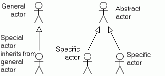
- List the actors in a Role Map, which shows the relationship between actors.
- Some roles encompass other roles: the special role can do what the
general role does, and more. The special role inherits
all the use case interactions of the general role.
- Some roles overlap each other. In this case, isolate the common aspects
in an abstact
actor.
- The use of generalizations
can simplify use cases. However, use sparingly.
- The open arrows indicate dependancy.
- Some people draw little houses for institutions as opposed to actual persons who are
drawn as a stick figure.
|
Role Map:
|
|
Use Case Packages
- Identify Use
Case Packages, which are manageable groups of use cases.
Often best to package by business use case[3].
- Identify the base System
Use Cases: the tasks that the actors will accomplish. Talk
to the users to get their tasks. Also think of events and requests that
the system must respond to. Generally, there is only one initiating
actor per use case. Remember: no details here (put them in a parking
lot). Compared to the business use cases, the system use cases are those
handled by a computer system, for example with a user sitting at a computer
terminal.
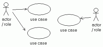
- Draw use case diagrams (see sample).
- Use verbs and objects in the use case names.
- Primary actors initiate the use cases.
- One actor can act on behalf of another: Actor A for Actor B.
- Secondary actors receive messages or reports. They may not always be
involved in every scenario.
|
Sample use case diagram:
|
- Describe and analyze the context:
i.e. how does the use case fit in with everything else. This includes
the actors (already defined), the triggers,
the pre-conditions
(what must be true before the use case starts) and the post-conditions
on success (compulsory outcomes if all goes well, the desired
outcomes) and the post-conditions
on failure (outcome if the process was cancelled or in the
case of an error).
- Then go into greater depth in each use case. Narrate the process from
start to finish, step by step. Start with the basic
flow, which is what happens when everything works "normally"
(happy
day scenario). Put other comments (the "if"s) into
the parking lot.
- Review the basic flow, and explore alternatives. At each step, ask
for other ways that the step can play out or what might go wrong. Also
ask for events that might happen at any time. These are alternate
flows (which lead to success) or exception
flows (which lead to failure). First list the alternates
and exceptions before going into detail.
|
|
- An inclusion
use case specifies behavior that is typically included in
more than one use case. It does not necessarily have to be a complete
use case. This allows for creation of re-usable code. Show with dashed
line and "«include»".
- An extension
use case allows that addition of requirements, without having
to re-write the whole use case. Show with dashed line and "«extend»".
- A generalized
use case is an abstract use case that describes the common
behavior of two or more similar use cases. Show with open arrow.
|
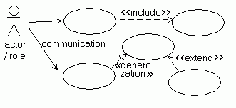 |
Note that there is no detailed information, no design of GUI, nor of data,
nor of security.
Scope
The use cases helps determine the scope.
Note: eliminate any non-IT processes, as these are studied in a business use
case (here we are talking about system use cases). Note however that the scope
is generally determined by the time the use cases are analyzed.
Study details of each use case
Now that the scope is determined, study each of the use cases within the scope.
Use a template and add one of the following tools for clarity. See next section.
Additional Documentation
Use cases complement additional documentation:
- Non-functional requirements, i.e. requirements that are not "observable",
such as security, performance, ...
- Business rules that apply across all use cases
- Descriptions of each user interface (the use cases are not useful for this)
- Project timetables
- Class models, activity and state diagrams
Projects include procedures like the following. In an effort to meet aggressive delivery schedules,
if these kinds of procedures
are sacrificed, there will be penalties to be paid in the future.
- Documentation
- Sign-off
- Testing
- Change management
- Source code control
- Change control
- Promotion procedures
- Metadata gives business and technical definitions for tables, data elements,
and other objects in data warehouse. This can include data lineage: transformations and
names of processes. The metadata system should include versioning.
- Document naming standards
- Key strategy (how to attribute keys, )
- Archiving and recovery plans
Specifics for Business Intelligence
Steps
- List and analyze the existing reports and data files
- Interview the business community; analyze what decisions are made now and in the future
The goal is to improve decision making:
"Providing an environment that positively impacts the businessís ability to
make better decisions must be an overarching, non-negotiable target; delivering anything less
is a technical exercise in futility for the organization."
Ralph Kimball's Design Tip #125 Balancing Requirements and Realities[7]
Use Case Description
Each use case is generally described using a template and a narrative account.
Then, if necessary, one or more of the following tools can be used:
- Dialogue table
- Activity diagrams
- Condition-response table
- Decision table
Template
| Template |
| Name of use case |
|
Description
1 to 2 paragraphs
|
|
Actors
List the actors involved:
- Primary actors. Note that only one primary actor can
initiate a use case (according to purists)
--> use a generic actor.
- Secondary actors
- Off-stage actors
|
|
Triggers
The trigger happens before the use case
and must be detectable by the system.
|
|
Pre-conditions
Conditions that must be true before
the use case begins.
|
|
Post-conditions
Post-conditions on success, i.e. conditions that must be true on successful
ending.
Post-conditions on failure, i.e. conditions that must be true when case
fails.
|
- Priority: essential, useful, nice to have
- Status, modifications, ...
- Expected implementation date
|
|
Context Diagram
Shows the related actors and use cases
 |
|
Basic Flow
Describe the normal flow of events.
Start each step with a number.
For each step, use at least a subject, verb and object to describe the
step.
Use a consistent tense.
Put "if"s in a parking lot for the next step.
Do not include details about GUI.
1. User connects to server
2. Server reponds with prompt
3. User enters name
4. ....
|
|
Alternate Flows
Describe alternate flows of events. Indicate the step for which it is
an alternative.
Alternate flows lead to a successful ending.
1a. New user: (this is alternate flow for step 1)
1a.1 Enter additional information
1a.2 Resume at ...
1b. ...: (another alternate flow for step 1)
1-2a. Single-Sign On: automatic connection (this is alternate flow
for steps 1 to 2)
Four situations for merging back into the flow: see below in "exceptional
flows".
|
|
Exceptional Flows
Describe the exceptions.
Exceptions lead to failure of the use case.
*a. Loss of connection to database: ...
(An asterisk indicates an exception that can
happen at any time).
Four situations for merging back into the flow:
- No indication: the alternate/exception flow resumes at the following
step
- "Continue at step nn"
- "Use case ends": the alternate/exception flow leads to an
end point in the flow.
- "Continue at point of divergence": typically for alternate/exception
flows that can occur at any moment in the use case.
|
|
Special Requirements
- Non-functional requirements such as security, performance, standards,
regulations, ...
- Constraints due to architecture, technology, ...
- Applicable business rules
|
| Activity Diagram |
| User Interface |
| Class Diagram |
| Open Issues |
A Dialogue Table / System Reponse Table
Describe user inputs and system responses:
| User |
System Response |
| Action by user |
What the system does |
| ... |
... |
| ... |
... |
Activity Diagrams
Activity diagrams describe either the scenarios of a use case or the sequence
of several use cases. They show mainly the workflow.
Use this when the workflow is complex.
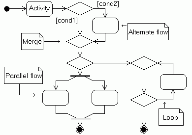
The start node is the full black disk. It leads to one activity followed
by a decision, with two conditions. This is an alternate flow. The UML standard
calls for a merge to clealy indicate where the two paths join again. The first
alternate flow is followed by a second decision. This leads to a parallel
flow on one side and to a loop on the other side. The two branches do not
merge and lead to two separate end nodes (final states).
Condition-Response Table
Prefer this for mutually exclusive factors that can be evaluated individually.
Prefer for situations where simple conditions determine the system's response
| Condition |
Response |
| The customer is local |
Outcome |
| The customer is not a resident |
another outcome |
| ... |
... |
Decision Tables
If a use-case is very complex, with many interrelated conditions, then try
a decision table. This covers all possible scenarios. Given n conditions,
there are 2n possible cases.
Use this table as basis for test scenarios.
| Cases |
1 |
2 |
3 |
4 |
|
2n |
| cond 1 |
Y |
Y |
Y |
Y |
... |
N |
| cond 2 |
Y |
Y |
N |
N |
... |
N |
| cond 3 |
Y |
N |
Y |
N |
.... |
N |
| |
|
|
|
|
|
|
| action 1 |
|
X |
|
X |
|
|
| action 2 |
X |
|
|
X |
|
X |
| action 3 |
X |
|
|
|
|
X |
Steps:
- Prompt users (or scan the requirements) for conditions that have a "yes"
or "no" answer; take apart complex conditions that have "and"
or "or". List these conditions.
- Prompt for all outcomes/actions and list them.
- Create 2n columns for all the possible combinations of conditions.
Fill in the "Y"s and "N"s in the 2n columns
corresponding to all possible cases
- Fill in the action boxes with "X"s
Structured Analysis (Data Flow Diagrams)
See also the notes on Source System Analsyis.
Also see notes on:
Structured analysis is generally used on legacy systems. It is not useful for
applications built with Object Oriented programming, for which UML is more appropriate.
Data Flow Diagrams (DFDs) are not part of the UML standard.
Start with a few high level processes, that each achieve a high-level task.
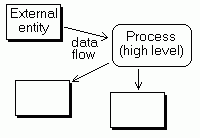 |
Level 0 (Context Diagram)
The arrows show the data flows, which are the movments of data (answers
to the question "what information is provided or received?").
The processes are the main data transformers, at a high level. The external
entities are people, organizations and computer systems that interact
with the system being studied.
As a BA, concentrate on the business processes. On the other hand, when
describing existing applications, the processes correspond to modules.
The level 0 diagram is also known as the context diagram.
|
| |
Use the level 0 diagrams to define the boundaries of the future system.
Review the level 0 diagram with stakeholders. By defining the external
systems, the boundaries are defined (external means outside, so what is
inside is what the new system will be).
In the UML world, the external entities are sort of like the actors,
and the processes correspond to use cases.
|
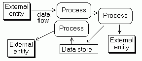 |
Level 1
Explode the processes into major processes. Show data stores, which
are where data is kept before being taken in by another process. Data
stores can be non-digital too. Each module performs a single task (maximum
functional cohesion), and each are independant from each other
(minimum coupling). The arrows show the flow of data, and the
label identifies the moving data.
|
| |
If necessary, explode the processes into lower level diagrams (levels
2 and 3).
The Gane and Sarson Notation shows datastores with a number in a little
box and processes as a box with round corners and a number. |
| A DFD follows some rules so as to ensure coherence: |
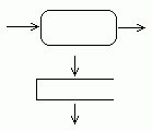 |
The processes transform data and therefore have data coming in and data
going out |
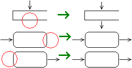 |
Data cannot originate in a process (it originates in external entities).
Data must flow out of processes and data stores. |
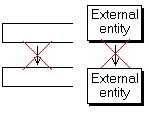 |
Data cannot move between data stores without a process in between.
Data flows between external entities are out of scope.
|
 |
Use case diagrams are comparable to level 1 DFDs without the data stores.
|
Bibliography
- Podeswa, Howard: UML for the IT Business Analyst. Thomson Publishing, 2005.
- Business Analyst Crash Course, www.butrain.com and www.nobleinc.ca
- [3] The Business Analyst's Use Case Workshop, www.butrain.com and www.nobleinc.ca
- [4] Gause, Donald D. and Weinberg, Gerald M.: Exploring requirements: quality
before design, Dorset House Publishing Co., 1989
- [5] Michael C. Reingruber and William W. Gregory: The Data Modeling Handbook,
a best-practive approach to building quality data models, 1994, John Wiley
and Sons
- [6] Graeme C. Simsion, Graham C. Witt: Data Modeling Essentials, Third Edition, 2005, Elsevier
- [7] Kimball Group Design Tips, part of the
Kimbal Group web site.
- M. Fowler: "UML Distilled", 1997
- Wiegers, Karl: "Requirement Use Case Analysis"
- Cockburn, Alistair: "Writing Effective Use Cases"
- Robertson, Susan: "Mastering the Requirements Process"
- International Institute of
Business Analysis www.iiba.com
- Object Management Group www.omg.org
(manages the UML specifications)
- www.acm.org
- www.ieee.org
- Software
Rquirements Management
